By Gary L Boehm
Gary L Boehm, PE Helical Products Company, Inc.
Wire springs appeared early in the Industrial Revolution and established their value immediately. The basic concept has not changed much, though there have been enhancements in materials and manufacturing. Typically, spring wire is coiled hot or cold with ends configured within the limits of coil wire, creating an industrial tool that exhibits elasticity.
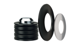
Machined springs function similarly to wire wound springs, but they are manufactured in a different way. Although any machinable material including plastics can be used, bar stock metal is the most common starting point for machined springs. The bar stock is first machined into a thick wall tube form. Then a helical slot is cut revealing multiple coils that when deflected, provide the desired elasticity.
The cost to manufacture machined springs exceeds that of winding wire springs. Wire wound springs can be created with just a few seconds of process time while a machined spring requires a minimum of several minutes. Plus, the machines used to create both forms are highly specialized.

Machined springs and wire springs function in similar ways, however, differences in manufacture affect their cost and suitability to various applications.
Spring into Shape
The coils found on wire wound springs are typically round. Sometimes they come in rectangular or rectangular with rounded OD and ID surfaces. These two latter forms are less common due to cost, however, they offer higher stiffness and are more compact than the typical form. The rectangular coils are normally used so that the long leg is radial, but the long leg can also be made longitudinal.
Rectangular wire comes in set sizes. You can venture from those sizes, but at an increased cost and lead time.
Coils used on machined springs are square, rectangular (radial or longitudinal), and trapezoidal. Trapezoidal coils are common to springs used in lateral bending and lateral translation. The shape allows for the additional lateral motion without coil contact. The size of the coil is easily changed to fit the spring’s needs. No standard sizes apply.
Slots. On wire wound springs the space between the coils (slots) is uniform for torsional springs and compression springs, but with compression springs the end slots tend to taper to zero. This process is called “closing” the ends, and is created by an additional forming process. Optional grinding makes the ends nearly flat.
Extension springs can have a uniform width from zero to most any size. If desired, the coils can be pre-stressed so that this spring shows a zero slot, however, you may need to exert additional force to overcome the coil separation threshold.
Currently, machined springs come with a minimum slot of about 0.020 in. (0.51 mm). Wider slots that do not exceed 0.250 in. (6.35 mm) are possible. The slot width can be closed to near zero using a stress relieving process, but no pre-stressing is currently available.
Number of coils. Wire wound springs can be made very long, such as garter springs for example. The quantity of continuous wire available on the feed spool limits this spring’s length. Machined springs are limited to about 30 coils depending upon size, however, rarely are coil numbers above 20.
In a wire spring, the entire length of the wire contributes to the elasticity because the forces and moments are distributed end to end with the ends providing the interface with adjoining equipment.
Machined springs are different. The flexure—the section providing the desired elasticity—is captive between the end sections, which provides structure and attachment. The end sections have infinite stiffness when compared to the flexure. Furthermore, the slots do not taper to zero at the ends; they remain at the full or initial width, as seen at free length. Thus, to achieve the same elastic performance, machined springs likely need to be longer than wire ones.
Precision. In general, machined springs can be made to precise dimensions more easily than wire springs. Both wire wound and machined springs readily offer a precision of 10%. Machined springs can offer 1.0% precision. Wound springs can too, when statistical methods are used for selection. A finer precision of 0.1% is probably not available from wire wound springs and only available from machined springs using post-processing techniques.
Cost. Production time is the major influence on cost. Wire wound springs have short production times. Machined springs cannot approach the low cost of wire product. It would be surprising to find a simple and inexpensive machined spring, produced in high quantities costing less than $2 dollars each. However, machined springs offer features that validate their use. These features include; integrated attachment points, higher precision, reduced assembly and acquisition effort, and quiet and clean contacts.
Usually, at least one of these benefits is necessary to justify the selection of machined springs.

Slot widths vary between wire and machined springs, even though these components have the same length, OD, and compression rate.
Material choices
Wire wound springs are typically made from medium and high strength steels, nickel alloys, titanium and stainless steels that have undergone heat-treating and cold reduction. Machined springs use somewhat similar materials. Spring wire and malleable bar are common to wound springs, but cannot be used for machined springs. A completed wound spring will retain various amounts of residual stress. While stress relieving processes can reduce residuals in wound product, the sum is not zero.
A machined spring with residual stress in the free state will be subject to freestate deformation, which is always undesirable. Materials subjected to solution annealing resist residual stress, as do materials that undergo heat treatment with no cold reduction or quenching. Quenching will, by itself, induce residual stress. Therefore, good choices are martensitic corrosion resistant steels (CRES) and martensitic steels.
Typical Machined Spring materials include moderate to high strength CRES, such as 17-4 PH per AMS5643, 15-5PH per AMS5659, CC455 per AMS5617, and very high strength steels like C300 per AMS6514.
Other good materials include 7075-T6 aluminum (high strength), 7068-T6511 aluminum (very high strength), 38644 Beta C Titanium (very high strength and corrosion resistant), Delrin 100 (machinable plastic), and Ultem 2300 (machinable plastic). Any machinable material that can be made free of residual stresses is a valid candidate for use for a machined spring.

Most springs have many types of end attachments. Hook and loop attachments are common for wire springs.
Improving spring materials
Wire springs are often shot peened to enhance fatigue resistance. The gaps between the coils are usually wide enough to let the shot pass through and condition the inside of the opposite coil, as well as the outside of the coils.
Machined springs’ coil slots are often too small to pass shot. Hence, shot peening is not common. Fatigue resistance often comes from stress relief holes and slots added to the slot ends. You can also select high strength, fatigue-resistant materials.
Wire springs can be plated with zinc and nickel for corrosion protection. Plating machined springs is uncommon because of the sharp edge corners, which typically receive insufficient coverage. The use of CRES and titanium materials provides excellent corrosion protection for most machined spring applications. Aluminum machined springs are typically anodized or coated to prevent corrosion.
Machine spring sizes are limited by machining practicality. The smallest springs are about 0.100 in. (2.54 mm) in diameter, and the largest are 6.0 in. (152 mm). Maximum length is about 24 in. (610 mm), but this applies to 1.0 in. (25.4 mm) to 3.0 in. (76 mm) diameter springs. Smaller or larger diameter springs will need to be shorter.

Wire wound torsional springs can have a rugged tang similar to that found in wire springs. Tang usage provides a moment force on a torsion spring.
Make the attachment
Wire wound spring attachments include compression springs, clipped end or natural, closed, and closed and ground. Closed and ground attachments are a little more expensive, but they provide the most perpendicular surface to the spring centerline.
While wire springs are limited to the use of wire form attachments, creativity has provided many, cost effective versions. Machined springs can possess any feature that can be machined.
Compression springs are fully machined. The ends can be flat and very perpendicular to the longitudinal axis of the spring. Extension springs can have machined studs, threaded holes, and flanges.
Torsion springs can have a rugged tang similar to that found in wire spring. Tang usage provides a moment on a torsion spring. To accomplish this, a force at a distance is employed. The spring provides the moment action, but needs additional reaction to the force. Typically, torsion springs using a tang rub on a guide on either the OD or ID to resolve this force.
In a machined torsion spring, a pure couple can provide the moment. A pure couple can come from double tangs (external, internal and longitudinal), slots, splines (internal and external) and bolt circle configurations. One can also resolve the moment by an integral torque restraint on the coil side.

Machined springs handle single and multiple starts. Multiple start springs allow for a pure force reaction.

Machined springs have their own attachments.
Multiple starts
While wire wound springs are limited to single start configurations, machined springs handle single and multiple starts. In the world of springs, the double start machined spring goes from basic function to concepts that are intrinsic to the function of mechanical devices.
Multiple start springs allow for a pure force reaction. A moment is created by compression or extension forces occurring at the spring coil’s width center, which is distant from the spring centerline. In multiple start springs these moments resolve to zero within the body of the spring. Hence, compression and extension springs with multiple starts provide elastic motion without the need of corrective moments. In single start springs, wound or machined, these moments must be resolved at the interface between the spring and the components providing the force and deflection.
Multiple start spring configurations unify the lateral bending and lateral translation forces and moments around a spring’s circumference given a lateral deflection. Configurations as high as five have been used to unify the lateral reaction of machined springs. Multiple Starts also add to the length of machined springs. Should a failure occur, the remaining coil(s) provide some functionality albeit degraded due to the missing coil.
Stresses in both machined and wire wound springs used in compression and extension are dominantly torsional shear. The maximum stresses are located on the spring ID and on the coil sides. It is very rare to find maximum stresses on the spring OD. Stresses at the sharp corners are functionally, very low.
Machined springs used in compression may benefit from stress relief holes (SRH) or elongated holes at the slot ends, but that is your call. Machined extension springs nearly always require a SRH, or equivalent, at the slot ends to mitigate the effects of harmful, tensile stresses. Without SRH, the spring’s performance must be reduced to avoid failure caused by the tensile stress riser at the coil ends.
Linearity of compression and extension springs is influenced by five factors: Geometric changes in the spring during elastic deformation from free length, residual stresses in the material, increasing coil contact during deflection (compression springs only), boundary condition fixation, and spring rotation during deflection.
When helical springs are compressed and extended, end-to-end twisting occurs. Three remedies exist with machined springs to eliminate the torsional deformation. Fix the end of the spring using any of the attachment techniques available. Or, constrain the spring end to increase the elastic rate. Or, use two concentric springs one with a right hand flexure and the other a left hand. When properly designed, the twisting of the inner spring counteracts that of the outer one. An option is to place two flexures on a single spring blank, one right hand and the other left hand. This configuration allows the interface between the two flexures to twist, but the ends do not.
Machined springs have a constant slot dimension, thus, there exists a slot width at both ends that does not close. When that dimension is added to the solid structural end, you’ll find that a machined spring used in compression is longer than an equivalent wire spring. This means that a machined spring cannot be configured to provide the same performance of a wire spring used in compression. Hence, in compression springs, equivalent machined springs are always longer than wire ones.
Compression and extension machined springs with multiple starts are successful in systems that operate at resonance. The features that contribute to this success include low tolerance elasticity, continuous slot dimension (no touching at coil ends at any time guarantees clean and quiet operation), internally resolved moments and uniform cross axis stiffness.
When considering any compression springs, review the issue of static instability (buckling). This issue becomes more prevalent as the number of coils increases. Because of their inherent stability, extension springs are not subject to bucking.

For compression and extension springs, flexure configurations help resist rotating deformation.
Machined springs used in torsion
Typically, torsional machined springs are a little longer than equivalent wire ones. These springs benefit from attachments, however, they differ from wire torsion springs in that the coil ID can be reduced to add stiffness to the torsional rate. Adding stiffness to wire torsional springs requires a change in the basic configuration, such as OD, ID, wire size, or number of coils, or a change in the wire shape. Wire is available in rectangular and trapezoidal sections. Trapezoidal sections are generally selected for smaller ID springs so that post wound sections will approach being rectangular.
If you want to double the stiffness of a torsional machined spring, double the coil thickness or employ a double start configuration using the original coil thickness for both starts. A double start spring would provide more stiffness, but it would also be more expensive, longer and possibly experience static instability (buckling).
Buckling is important in torsion springs and becomes an issue when the number of coils increases and the coil width decreases. Both wind-up and unwind directions should be analyzed for buckling.
The maximum tensile beam stresses are located on the OD when the spring is subject to windup deflections; conversely, the stresses on the ID are at maximum compression. When the spring is subject to unwind, the stresses are the opposite. It is critical that there be no nicks or cuts at the area where the stresses are at maximum. These flaws would increase the stresses, and possibly initiate cracks. For the same reason, machined torsional springs should contain stress relief holes or slots to help mitigate “stress risers” as the coil section changes into the solid structural section of the spring end.
If a machined spring were subject to equal deflections in wind-up and unwind, stress would be considerably higher in the unwind condition. Geometry causes this situation and is unavoidable.
If a spring is anchored at one end and the other is subject to a moment, the load case is labeled as lateral bending. While it is possible to subject a wire spring to lateral bending, machined springs are more commonly used because of their numerous attachment options. Buckling is rarely a concern for lateral bending springs.
Lateral Translation occurs when one end of a spring is anchored and the other end is laterally displaced by a force plus a moment to insure the end faces of the spring remain parallel. Such deflections are better suited to machined springs because of attachment options. Similarly, buckling is rarely a concern for lateral translation springs.
At one time wrap spring clutches were major components in motion control systems, but with the growth of electronic motor controls, the demand for wrap spring clutches has declined. However, markets such as avionic flight controls prefer these devices because of their nonelectrical needs and rugged nature.
Wrap spring clutches function basically in two ways. They engage and disengage torque transfer in a torque line by the selection of rotation direction and engagement or disengagement of a tang. The avionic industry has a component called a No Back that limits the amount of torque transferred in a torque line and is used to protect flight controls from damaging, over-torque situations.

Here’s an example of machined springs used as a no back and wrap spring clutch.
Working the math
Much analytical work has been accomplished by such experts as A. M. Whal, S. P. Timoshenko, and J. N. Goodier. The SAE provides design guides in the Spring Design Manual AE21, the Spring Manufactures Institute, and others. For the most part, all this work provides closed form equations for wire products. Since the geometries can be similar between wire and machined springs, it is not uncommon to try to use the equations sets for both.
With machined springs, though, closed form equations may not fully apply. The equations do not account for all boundary conditions and actual geometries for wire springs. Displacement affects geometries, and must be included in the computations as well.
Closed form solutions for machined springs may be inaccurate. As a general rule, equation accuracy wanes when the number of coils is less than three or the ratio of coil sides exceeds two, height to width. For these reasons, quality FEA is nearly always needed for elastic and stress computations related to machined springs.


Hi,
My name is JD Wriston, I am the Technical Director at Maui Divers Jewelry in Hawaii. We are making a line of spring loaded hinged bracelets. I would like to use a leaf spring rather than a coil spring as we could make a sleeker, streamlined bracelet. I am looking for flat spring wire that is about 2.5mm wide and 0.5mm thick, we will cut the length and form the desired curve. Will you please recommend a spring alloy for us to purchase? I’m looking for a non or anti-corrosive alloy that has a very low level of fatigue. Thank you in advance for your help with this.
Best Regards,
JD Wriston